I/O Allocation
ControlEdge Transition enables you to allocate I/Os in one of three ways:
-
One to One Allocation
-
Smart I/O Allocation
-
Manual Allocation
One To One Allocation
The source PLC system I/Os are mapped to their ControlEdge I/O equivalents based on a mapset that has been already created.
ControlEdge I/O Allocation Rack Sizing
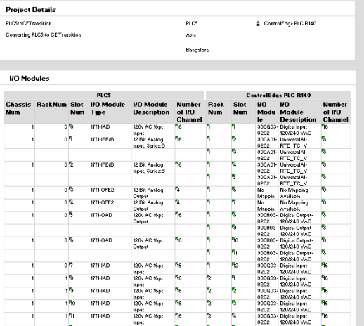
Calculate number of racks required and type of racks (4,8 or 12 slots) by getting the total number of modules required for each chassis in the source system.
Create One To One I/O Allocation
First all the source IO is listed and then ControlEdge PLC CPM equivalent is mapped to target system I/O properties based on rack sizing and the number of modules required. The source I/O chassis is mapped to ControlEdge PLC CPM's racks.
Create One To One I/O Channels
Based on the One To One I/O Allocation details, channels are generate by target system's number of channels required for a module. It shows I/O module allocated to each rack number alongside I/O Module Description.
ControlEdge PLC CPM's channel details can be edited & updated.
Follow the steps for allocating One To One I/O Allocation:
-
Click
 and select One-to-One, the One-to-One I/O Allocation dialog appears.
 -
Click I/O Modules or I/O Channels tab to view the I/O Modules and I/O Channels assignment. Click OK.
Smart I/O Allocation:
The tool maps source PLC or SLC system I/Os with ControlEdge I/Os taking into account all the added features and functionality offered by ControlEdge. There are four rules in Smart I/O Allocation. The rules with examples are given below:
Rule 1 : Combine adjacent modules of the same type within a Chassis
As shown in the figure, you can combine two adjacent I/O module with same model from the same chassis. According to the figure, 1771-OFE2 I/O Module occur in same Chassis Number 1 and are adjacent, this can be combined using the Rule 1.
Rule 2 : Combine modules of same type within a Chassis
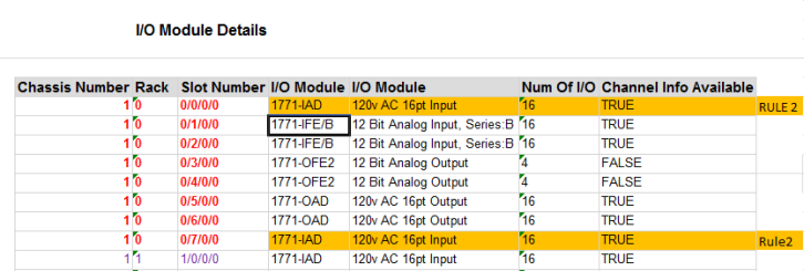
As shown in the figure, you can combine two I/O modules of same model occurring in different slots if it is within the same chassis. According to the figure, 1771-IAD I/O Module occur in same Chassis Number 1 but are in different slots not adjacent and can be combined using the Rule 2.
Rule 3 : Combine modules of same type across Chassis
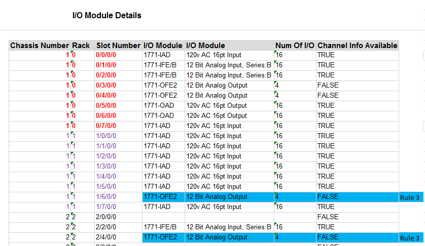
As shown in the figure, you can combine two I/O modules of same model occurring in different slots even if they are in different chassis. According to the figure, one 1771-OFE2 Module occur in Chassis Number 1 and another 1771-OFE2 Module occur in Chassis Number 2 even then they can be combined following Rule 3.
Rule 4 : Combine Universal I/O modules within (or) across Chassis
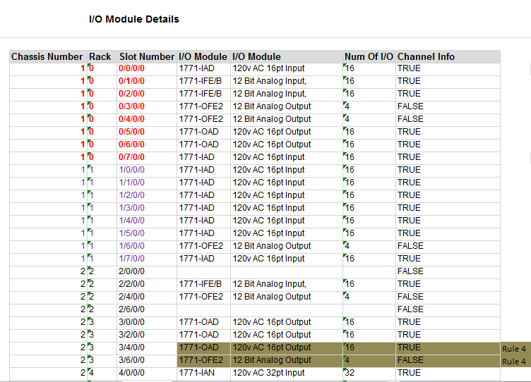
As shown in the figure, you can combine two UIO modules of different model occurring in different slots even if they are in same or different chassis. According to the figure, one 1771-OAD Module occur in Chassis Number 2 and another 1771-OFE2 Module occur in Chassis Number 2 even then they can be combined following Rule 4.
For all rules CE PLC Module should have capacity to accommodate all channels.
Create Smart I/O Channels based on the Smart I/O Allocation details, channels are generated by target system's No. of Channels required for a module. ControlEdge PLC CPM channel details can be edited & updated.
Note that, in the case where none of the rules are selected then One to One I/O Allocation data is populated. When all the rules are selected then only Rule 3 & Rule 4 will be executed. When Rule 1,2 & 3 is selected then only Rule 3 is executed. Rules are applied in the order Left to Right and Top to Bottom.
For example, if the source PLC system had 8 I/O channels and used 2 I/O modules (4+4), smart allocation uses one UIO and assigns all 8 I/O channels to a single UIO, thereby reducing 2 I/O modules to one UIO module.
Follow the steps for allocating Smart I/O Allocation:
-
Click
 and select Smart, the Smart I/O Allocation Input dialog appears.
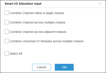
-
Select the target rules, and click OK to view the I/O Modules and I/O Channels assignment and click OK. In this method, the IOs in ControlEdge PLC are allocated after utilizing the enhanced capabilities of ControlEdge.
For example, the number of IOs needed comes down because of ControlEdge's UIOs which have 16 channels. View the I/O Modules and I/O Channels tab and click OK.
Manual Allocation
You can manually allocate source PLC system I/Os to ControlEdge equivalents. To begin, click Manual Allocation. A window appears and provides you the choice between one to one allocation or smart allocation. Choose one of them and continue to allocate the I/Os.
You can manually edit & map with Group Number, Rack No & Slot No based on target system. User submits for validation of mapping.
While using Manual Allocations the following validation methods are used:
- No of slots per rack i.e. 4,8 & 12 slots per rack.
- Input always must be greater than zero for Group Number, Rack No & Slot No.
- Input must not have multiple Rack No for a Group Number.
- Sum of PLC I/O Channels cannot exceed Sum of ControlEdge PLC I/O Channels.
- Input is mapped with same source system module.
Based on the Manual I/O Allocation details, channels are generated by target system's number of channels required for a module.
Follow the steps for allocating I/O:
-
Click
 and select Manual, the Select Data Source dialog appears.
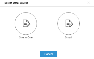
-
Click One to One or Smart to view the I/O Modules and I/O Channels assignment and click OK. In this method, you can perform I/O allocations manually.
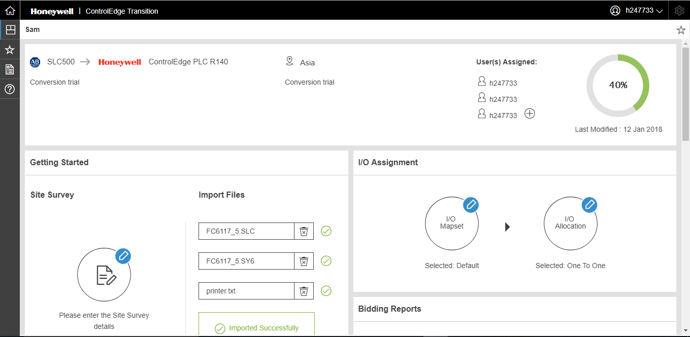
I/O assignment is complete. You are ready to generate bidding reports.
Status completion is shown as 40%.